Vulnerability Propagation Tool
The main goal of the propagation tool is to find and indicate the components or elements a single vulnerability can affect, and therefore, its path within the system.
The calculation of the path affected by a vulnerability is characterized by the source code of the system and the location of the vulnerability along the same. These will be the required inputs for the developed tool. Thus, the location of the vulnerability is identified by a function of the source code of the program to be analysed, or by an external library that is being used. In the latter case, for example, all the elements related to the use of that library can be affected.
Having these input parameters and taking into account the state of the art on the subject [3], it has been decided to develop a propagation tool based on graphs techniques. The calculated graphs will allow to obtain a roadmap of the code under analysis and, therefore, of its structure. These will be use as a basis to mark the path followed by the indicated vulnerability. After a previous study on different code representation techniques [4, 5], a combination of them has been chosen, which has led to the design of a tool based on 3 phases (Figure 1):
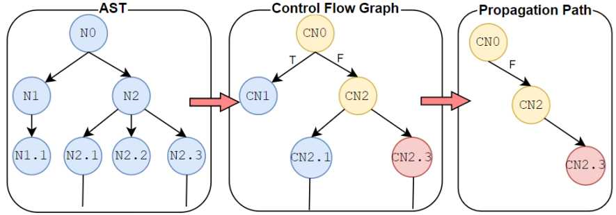
In the first phase, the tool starts to elaborate the AST by performing an analysis on the system source code, i.e., analyses the source code of the program and performs a tree representation. In the second phase, new nodes with the useful information are created based on the AST. In this way, a CFG of the source code of all the elements of the system is obtained. Subsequently, after obtaining this CFG of the analysed system, the location of the vulnerability is indicated to elaborate its corresponding path through the CFG. To do this, the tool goes through all the connections that the vulnerability has on the previously created flow. The propagation tool obtains as a result the control flow detailing all the elements, from the first instruction at the beginning of the program to the element where the vulnerability is located. An example of the process can be found in Annex A.
These elements related to the vulnerability can been seen as the possible steps an attacker could follow until reaching its possible exploitation. Thus, indicating this path, the developer can identify which part of the flow modify in order to mitigate the
vulnerability. Therefore, the propagation tool offers the developer a perspective of preventing vulnerabilities in the system.
Next, the generation of the different representation in the steps of the tool are explained in more detail.
AST generation and Logic Nodes
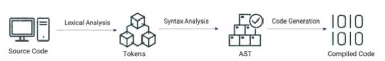
AST is a representation of the abstract syntactic structure of the source code written in a formal language, where each node of the tree denotes a construct occurring in the code. When it comes to the conversion of the code to some intermediate representation, such as machine code, three intermediate steps are carried out (Figure 2) :
• Lexical analysis: transformation of characters into tokens that can be used for syntactic analysis. These tokens describe the different parts or components of the code.
• Syntax analysis: Transformation of the tokens into a data structure. i.e., AST . This code structure identifies the type of code involved, like function call, variable, etc. The AST is composed of nodes that specify what they represent. Code transformations or analysis of the code can be performed on this structure.
• Code generation: The previous structure is transformed into source code. This new code may not be the same as the one used for lexical analysis in case any modification has been made on the AST.
As previously mentioned, the propagation tool creates a syntactic tree or AST where the abstract syntactic structure of the source code of a programming language is represented in the form of a tree. Each node of the tree indicates an instruction that occurs in the code, with each new block of code being a new level of children within the tree. It should be noted that, in the AST, not all details of the actual syntax of the source code are represented .
To start creating the AST for the propagation tool, nodes that compose it are elaborated. Each node refers to a different source code instruction that is related to each other taking into account the execution of the program.
Figure 3 shows an example of a code to be analysed that contains a vulnerability in the marked line, and from which the AST is obtained by the propagation tool (Figure 4).
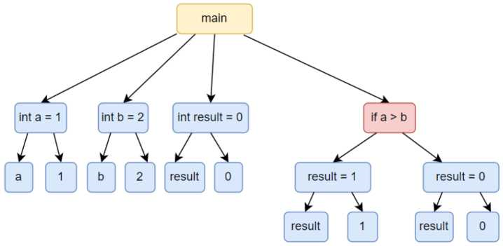
As can be seen in the example, a part of the code is shown where the principal node is the “main”. Within this node, there are 4 lower nodes, that is, 4 instructions that are executed. However, from the perspective of the AST, a new level of 4 children is created having all as parent the “main” node. The relationship of these nodes is represented through the parents and children that compose a syntactic tree. These 4 child nodes related to the “main” node are the following:
• int a = 1: Declaration of a variable called “a” of type integer with the assignment of a value of 1.
• int b = 2: Declaration of a variable named “b” of type integer with the assignment of a value of 2.
• int result = 0: Declaration of a variable called “result” of type integer with the assignment of a value of 0.
• if-else: conditional statement where a comparison is made with the variables “a” and “b” previously declared, so that if the variable “a” is greater than or equal to the variable “b”, the variable result will take a value of 1. If this comparison is not satisfied, the “else” block is executed where the variable “result” will take the value of 0.
Within the conditional statement, two branches are created by the content of the if-else blocks. Each of these branches derives to a different node, taking into account the possibility that the comparison is fulfilled or not. In this example case, the two nodes interpret the value taken by the result variable.
If the vulnerability is identified in the if comparison, where it is verified that the variable a is greater than or equal to the variable b, it is possible to obtain the elements related to it and to provide to the developer the necessary information to be able to mitigate the vulnerability in a simple way.
In the case of this example the vulnerability is located in a conditional statement. However, and as mentioned above, the vulnerability will be identified by a function, that is, it will not be identified by a specific line of code, but by the function that contains that line of code. For this reason, the AST will be created on the source code of the system file to be analysed and of which the vulnerability has been identified.
Within the framework of BIECO, the creation of a propagation tool which supports different programming languages has been proposed. To do so, and due to the existing structural differences between languages, different tools have been developed when extracting the AST depending on the language to be analysed. Currently, the tool is developed to support code files in Java and Python programming languages. The methodology used to create the AST in the two different programming languages is explained in detail below.
2.1.1 Java code
To perform the AST on Java code language, the open-source Java library JavaParser has been implemented. The process followed by this library is the execution of the source code of the chosen program file to later analyse and parse it in an automatic way, thus, creating the AST with the information from the source code. In addition, using the API of this library and the obtained tree, several operations can be performed on the AST, such as traversing it, or modifying and deleting nodes of the tree.
It should be noted that, in addition, this library offers the functionality of transforming an AST modified with the operations indicated above back to Java code, where the program will be created with the indicated modifications.
In the case of the creation of the propagation tool, the last-mentioned functionality of the library of transforming the modified tree into source code is not used.
2.1.2 Python code
Python language has a large number of functionalities and modules within the language library itself, which can be freely used by the developer. For the creation of the AST in the Python programming language, the ast module is implemented, which is responsible for processing abstract syntax grammar trees of Python applications. This module obtains the program grammar independently of the Python version used .
The process followed by this module is the same as the one followed to create the AST in Java. First the ast module is given the source code to be analysed. This code is analysed and parsed automatically obtaining the AST that indicates Java, this module allows the operation of traversing the nodes of the AST but does not allow modifications.
Once the AST has been created, it has been implemented a pre-processed of the same to unify the AST of different programming languages in the same format. This standardization will allow a better management of the data in the next phase of the tool since it saves the need to indicate the source code language. For its development, it has been performed a pre-processing of all the nodes of the initial tree, focusing on their logic. This pre-processing generates new nodes, called Logic Nodes (LN), which provide an easy way to transverse AST nodes by focusing on the logic level. This makes it easy for developers to get a clear view of the AST that represents the program.
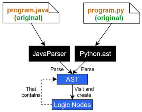
The process for obtaining the final LN is shown in Figure 5. In it, the corresponding Python or Java library obtains a file of source code, parses it and creates an AST. The propagation tool visits this AST and creates its LN by wrapping the AST, allowing it to be accessed logically.
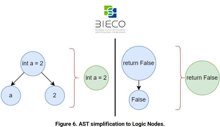
An example of this simplification is shown in Figure 6. It presents two possible cases: one that shows the simplification of the three nodes that compose the assignment instruction into a single node (left side), and another that represents the two nodes that compose the return instruction simplified into a single node (right side). As it is possible to observe, green nodes, which are used for the creation of the new tree, do not provide as much detail as the nodes that the initial AST has, in blue, about the name of the variables, the value assigned to them or the return value in a function.
2.2 CFG generation
Once the LNs have been obtained, the CFG is generated. This graph only contains the information about the logic of the code under analysis. In this way, it is possible to have the entire control flow of the whole system to analyse, regardless of the number of files it contains .
The CFG is created from the union of the LNs. To do this, the LNs, which are initially partially interconnected with each other, use the system information to complete the possible relationships existing between them. The relevant information that has been taken into account when creating the CFG are the nodes that affect the logic of the program as those structures that imply a conditional statement or loop, such as if-else, while, or for between others. In addition, for this tool, the calls and outputs to functions, such as instances to objects and methods, have also been taken into account in order to explore the logic of the program in its entirety. This inclusion will be useful when extracting the propagation path.
It is notice to mention that one of the innovative points in the development of this tool is the integration of the possible exceptions within the CFG. When programming, the use of exceptions to manage the logic of a program is not a good practice, which means that this functionality is not considered when generating the CFG. However, many developers include exceptions to handle the logic of their programs. For this reason, it has been decided to include these practices within the CFG since exceptions transparently verify to the developer if there has been an error and can affect the logic. This ensures that no logic is left unrepresented within the final CFG.
If the program to analyse has a main function, the CFG shows two auxiliary nodes that indicates the beginning, called entrypoint, and the end of the execution, called stop. If did not have any executable, (e.g., there were only methods for another executable file to use them) the CFG does not show the two auxiliary nodes.
After the generation of the CFG, a file with the results is provided to the user in three different formats:
• A JSON format, that provides a lightweight data interchange format. This structure is easy for machines to parse and generate. JSON is a text format that is completely language independent. This format shows the CFG in a simple way for both humans and machines.
• A PDF where the CFG is reported along with arrows that relate each of the nodes and indicating the path that could follow. For example, in the conditional sentences, it is indicated whether or not the condition is met and the node that is executed.
• DOT which uses the graphviz library and is used as a standard representation to generate and represent graphs whose format is .dot. This format makes layered drawings of directed graphs. The layout algorithm orients the lines in the same direction and tries to avoid line crossings and reduce the length of the lines. A text representation can be converted from a text representation to a pdf format document through this library.
An example of a PDF file of a CFG is shown in Figure 7.
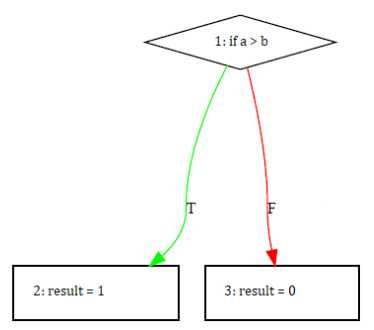
In this example, it is shown a node with a conditional if statement that has the comparison of two variables a and b, from which two other child nodes are derived. Each child node is executed depending on whether the condition is satisfied or not. If the condition is satisfied, the execution follows the green arrow (indicated by the letter T coming from True) and node 2 is executed assigning to the result variable a value of 1. If the condition is not satisfied, node 3 is executed assigning to the result variable a value of 0. The information of the arrows when a condition exists (T or F) is also reflected in the AST, but not as clearly as it is shown in the CFG.
2.3 Propagation path
The last phase of the process followed by the propagation tool is to obtain the propagation path. This path is determined from the main node to the location of the
vulnerability, i.e., the control flow that follows the execution of the program from the beginning until it reaches the node containing the vulnerability will be shown.
To obtain the propagation path, it has been designed a tool that pointed the node that contains the vulnerability and runs backwards until it reaches the first node of the program. In the case of containing an executable, the path would run from the vulnerable node to the initial entrypoint node and covers the affected nodes. If it is not possible to reach the initial node because of the large number of affected nodes, the maximum number of them will be shown starting the reverse path from the vulnerability.
The propagation tool will show all the paths that the logic of the program has to follow in order to reach the vulnerability, since what is beyond the vulnerability may never be executed once exploited. The developer could then detect the issue and see what preventive measures to implement in the program in order to mitigate this vulnerability and thus prevent the system from being exploited.
The process to follow for obtaining the propagation path is to traverse from the vulnerable node to the first node of the CFG based on the program. The nodes traversed in this third phase will have an active vulnerable field, so all the nodes that have this field active will be the ones that appear in the path. The rest of the nodes will be omitted as they are not part of the identified vulnerability. In this way, a reduced CFG would be obtained. This output would be provided in three different file formats indicated in the CFG section, i.e., JSON, PDF and DOT.
The implementation and development of the propagation path will be the focus of the D3.6.